(THIAGO FLAFKF)
The information show in this section of the document will mainly focus on modular modeling. To start of the research Charlie Lambert will look at a website named ‘THIAGO FLAFKF’. This website shows how to create a sci-fi looking environment using modular modeling and also looks at using this in UDK.
The information show in this section of the document will mainly focus on modular modeling. To start of the research Charlie Lambert will look at a website named ‘THIAGO FLAFKF’. This website shows how to create a sci-fi looking environment using modular modeling and also looks at using this in UDK.
 |
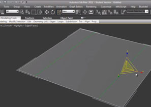
Image 001 – Thiagoklafk explains on his webpage about Bounding
boxes, which is what is displayed in the image above. The image shows
that “bounding boxes should contain inside the 1x1
piece aspect ratio” (Thiagoklafk).
|
The website explains how to create modular environments in UDK, however Charlie will be working in 3Ds max when following this tutorial raver than UDK.
The site states “the most important steps when working with modular sets is to invest a lot of time in planning” (THIAGO KLAFKE) this is due to the face that some pieces will look quite nice when modeled individually though might look awful when tiled.
 |
Image 002 – when using the 1x1 aspect ratio it is not necessary
to use x, y, z within it. This is as shown above, as this has been
followed to create the wall pieces, which have been created.
Using planes.
|
Pivot Placement is important as it will determine how easy it will be to place the pieces created into the level. The website explains about ‘a general rule of thumb’ which is to place it in one of the plane extremities. This method is better than placing it in the center of the mesh as it makes scaling easier to rotate and scale.
 |
Image 004 – to the left is an image that shows where to
place the pivot for the best results. |
This is clearly demonstrated in the images to the right. As the pivot has been placed on the bottom corner to make it easier to rotate the wall into to correct position.
 |
Image 005 – the image above shows that to pivot has been
place in the corner which makes it easier to create a
circular shape.
|
When modular modeling, it is a good idea to reuse textures for different pieces as it will use less render time when placed in game. The textures that the artist demonstrates in (images 006) are to different texture, however the textures are used together to create a large verity of textures. Texture one is a 4 directional tiling texture and texture two are different trim textures.
Creating materials in UDK, in this area of the tutorial the artist explains about cube mapping and how to set up a material in UDK. First Charlie will have to create a cubemap entity.to do this she must
· Right click the content browser and create a new Texturecube.
· Then she will have to set all the faces of the cubemap and finally save it
This process is demonstrated in the image to the right
All images and information was taken from the link below if you wish to follow the tutorial that i have followed please go to the link below:
http://www.thiagoklafke.com/modularenvironments.html
Paul explains in his video that he could have made the path and road as different modular pieces, however in for this piece he decided to create them together to save time.
If this tutorial by Paul Roberts, looks helpful to you and you wish to follow this tutorial properly for your self then please go to the following link:
if you want to follow this tutorial for your self then please go to this link
http://philipk.net/tutorials/modular_sets/modular_sets.html
I will not be showning any content from the next tutorial that i followed as it is not a free tutorial if you want to buy the tutorial to follow it then i will be happy to leave the link to the tutorial set below
http://www.3dmotive.com/training/udk/modular-building-workflow/?follow=true
Gizm0san
To make the
particle spawn in multiple places rather than one he adds initial location be
right clicking the particle Colom. This will change when the dust particles
spawn. He changes the max of x, y, and z to 500 and the min of x, y and z to
-500.
 |
Image 014 – the image shows Charlie’s
design of a doorway,which was created
using the same method that THIAGO using
in his tutor.
|
After completing research on THIAGO KLAFKE Charlie will know follow to tutorial her-self. The area of research shows Charlie’s work based on the tutorial shown previously. The images resemble THIAGO KLSFKE but have been changed slightly to show that Charlie has followed the tutorial and not just copied the modelers work.
 |
Image 014 – to create this corner Charlie placed the pivot point
onto a vert in the lower corner, then used the rotate tool to create
a copy of the wall and a corner as well.
|
 |
Image 014 – to create this wall Charlie create three copies of
the wall and positioned them as shown, then she used the bend
modifier one the piece in middle to create the curved corner.
|
(Paul Roberts)
 |
Image 018 – The artist starts by creating a single square
plane, size 512 by 512 .
|
This tutorial focuses on building a road using modular modeling. Paul explains how to create a straight, 90c bend and T-junction road. When building the road Paul tells the views that he is basing the size of the model on what the human size is for UDK, Which is 96 units high. Using this information Paul starts by create a plane that is sized (512 – 512).
 |
Image 019 – Once the edges are connected Paul then
extrudes the polys on the sides so that they look more
like a path
|
Paul explains in his video that he could have made the path and road as different modular pieces, however in for this piece he decided to create them together to save time.
Paul makes the plane an editable poly then selects the sides and uses connect, to create the pavement he goes in the connect settings and creates two segments and pinch to create a good with or the pavement.
After this step Paul then connects the edges on the middle poly. This time pinch and slide is at zero and three segments .
Before continuing Paul decides to chamfer the edges that make the curb of the road, he does this so that it looks better when the light hits it. In order to create new shapes for other parts of the road , Paul goes to border and selects the edges around the bottom, then holds down shift and drags the edges down to create side polys. This is shown in the image to the right.
 |
Image 021 – selecting the polys that make up the road Paul creates a curve, he does this using the FFD 3x3x3 modifier, then pulls the middle verts up the create a more believable looking road.
|
 |
Image 022 – Paul deletes unwanted polys and then selects
the side polys to create more modular pieces
|
 |
Image 023 – Paul then makes a copy of the selected
polys to create a new object.He does this so that he can create
different pieces of the road.
|
 |
Image 024 – new that this new shape has been
created he uses the profile to create a bend, to
create the bend he using the hinge tool. He selects
one of the sides to create a 90 degree angle.
|
 |
Image 025 – to give the shape a more rounded look
he adds about six more segments to the object.
When he has done he then deletes the unwanted
polys.
|
 |
Image 026 – after deleting the polys, he makes the outer
part of the path more square so that it is easier
to place buildings around it.
|
 |
Image 027 – the image above shows what Paul has
created once finished, however he starts this model again
and adds an edge loop around the path polys to make
unwrapping easer later on.
|
 |
Image 028 – after completing the second object he moves
onto the third one, this part of the road is the t junction.
To create the junction he adds a
symmetry modifier to the model.
|
 |
Image 029 – after applying the symmetry modifier paul starts
to delete more unwanted polys. These polys need to be deleted as
there aren’t in the right place or facing the right way.
|
 |
Image 029 – the deleted polys are replaced with new polys.
These poly are straight rather then curved like the old ones.
|
 |
Image 030 – after replacing the polys the model is finished
and ready for unwrapping and texturing.
|
If this tutorial by Paul Roberts, looks helpful to you and you wish to follow this tutorial properly for your self then please go to the following link:
http://www.youtube.com/watch?v=mMkgJg9HDN0
Philip starts his tutorial by asking himself one simple question which is “What type of set will you create?”.(Klevestav, P. NA). The artist starts with a basic panel that he has created, this is seen in image45. Philip explains that the tutorial has been set up into different sections, so that he can explain thing about modular modelling easier.
 |
Image 045 – the image shown is of a simple wall panel that the
artist uses as a spaceship wall.
|
Philip informs the reader that there are two spaces that he will be working with and also tells the reader that he always sticks to the grid when modular modelling. The two shapes are as shown as red and yellow in the image to the right.
 |
Image 046 – The two shapes that are coloured red and yellow can
be cut, flipped and rotated to create a number of different units.
|
After creating the wall piece Philip moves on to Photoshop to create the texture for the model. Philip mentions that he likes to work on his texture simultaneously as he is building the geometry. He also says that when modular modelling spending a large amount of time on a high poly model, but instead work with that in a modular way as well.
 |
Image 047 – the image shown above is the texture that Philip uses
on the model used in his tutorial. He has used different layers to
create the texture.
|
 |
Image 048 – this image shows three different maps, a texture specular and normal map all of which can be made in Photoshop using the right Photoshop add-ons. Maps can be created in many different ways wich will be explained more in depth later in the document.
|
 |
Image 050 – in this image Philip shows the viewer what the wall piece looks like when place together and modified to to look like a corridor. The artist used a bend modifier to create a curved wall.
|
 |
Image 051 – the texture shown in this image is used to break up the
reputation on textures. “It is also a great way to quickly try out
new shapes ingame where you just boxmap a tiling texture and
paint some ambient occlusion using vertex colours.” (Klevestav, P. 2010)
|
After taking the reader thought texturing, Philip moves on to talking about breaking up the repetition of the textures and modular pieces. A good why to break up repetition is to vertex colour your meshes, this is if people have and engine that uses vertex colouring.
 |
Image 052 – Philip suggests that if the set that has been create is used
a lot in a level then adding addon units will help create a better,
less repetitive look. For example simple textures (shown above) can be
used and are known as decals.
|
 |
Image 053 – the image shown above shows how the artist work
looks in UDK. Philip explains that it is a good idea to place
objects into a UDK level as soon as they are finished and ready
to be put into the level.
|
http://philipk.net/tutorials/modular_sets/modular_sets.html
I will not be showning any content from the next tutorial that i followed as it is not a free tutorial if you want to buy the tutorial to follow it then i will be happy to leave the link to the tutorial set below
http://www.3dmotive.com/training/udk/modular-building-workflow/?follow=true
Gizm0san
 |
| starting with the smoke texture Gizm0san builds up that material using the material editor |
In this tutorial Gizm0san takes us though creating a particle fire within UDK. He talks us thought the process of making the fire in simple easy to follow steps. Firstly he imports the two textures that he will be using for the tutorial and makes a material with them. Starting with the smoke texture, he opens up the material editor and places the texture in the editor window.
 |
| This is what the material editor will look like when the material is finished. This is how the glow ball texture will look as well. |
To make the material Gizm0san adds a constant that is a value between 1 and 0,(0 is black and 1 is white), vertex colour this will allow me to change the colour in the particle system, multiply x3. He starts editing the texture by changing the constant to white and connects the texture to one A on one of the multiply panels and connecting the constant to the B of the same multiply panel. He the connects the connected multiply into one of the other multiply panels and then connects that multiply into the colour vertex panel. He then connects the multiply into the emissive channel as particle effects don’t show defuse channels. He then connects the final multiply channel to the texture and the colour vertex. Gizm0san also connects the third multiply to the opacity channel as well.
 |
This is the particle editor to create a new particle Gizm0san
right clicks and selects create new particle.
|
This is the part of the tutorial where gizm0san talks us thought how to create the particle effect. He explains how everything works and what it does then starts by selecting the material in the content browser and adding it to the particle system and then restarts the simulation to view the effect. After this he changes the initial size of the particle, X = 100, Y = 0, Z = 0 max, X = 80, y = 0, Z = 0 min. velocity X= 20, Y = 20, Z = 100 max , X = -20Y = -20 and Z = 50 min.
 |
| the particle effects starts to look and move more like fire the next step is to change the colour. |
The next area to edit is the colour over life panel. He changes the colour to orange by using the curve editor. To use this he clicks on the small square on the colour over life panel then moves the red and green square up in the small box in the bottom right until he gets the colour he want. Gizm0san turns of the alpha channel so that he doesn’t move that by mistake. When he is finished with the colour he messes with the alph channel to make it fade in and out, this gives the particle a move fire like look.
 |
| now that the colour of the particle has been change to a red/ orange colour it looks more like fire. |
Following this a initial rotation is added so that the fire will flicker to the sides. He sets the rotation max to 1 and min to -1. He then adds a rotation rate that spins the particle setting max 0.2 and min -0.3. After this he moves on to create embers and smoke however I will only be following the tutorial till he has created the ember as the smoke is not need for what I want.
Gizm0san adds a cylinder channel to the fire, which will make the fire particle spawn in more than one place with the cylinder. In order to see the cylinder Gizm0san checks the box next to draw 3d mode. He then changes the radius to 30 and height to 20. Doing this makes the particle look less like fire so Gizm0san changes the spawn rate from 30 to 50. He then decided to increase the velocity change the min to Z = 100 which makes the particle look more like fire.
 |
Gizm0san added an effect that makes the fire
spawn in more the one place
|
Moving on Gizm0san selects the glow ball material in the content bowers, then right clicks in the particle editor to create a new particle system. This will make the glow ball the texture for the new particle system. The glow ball is too thick as they are so they need to be made thinner. This is done by going to required and change it from screen alignment to velocity. Then moving to initial size he changes max X = 10, Y = 10, Z = 25, min set to X = 2, Y = 10, Z = 25.
 |
| The particles in this image will be used as fire embers that will come of the firer. |
The next thing to sort out is the spawn points of the ember. Gizm0san explains that the embers should spawn the same as the fire particle. The easiest way to do this is to select the cylinder on the fire particle, alt left click and draw over to the ember particle. The cylinder for the ember is made smaller. The colour is then changed to match the colour of the fire.
 |
| The spawn location and colour of the embers have been changed to match the fire particle. |
 |
Image 66 – this
is how the particle looks in the
editor before drew starts to edit it.
|
Drew Danielson
Draw starts of by creating a new particle system. He then explains about changing the diameter of the particle as its known good at it is at the minute. He starts by going to spawn and then adjusts the spawn rate, increasing it to 50. He then moves on to change the life time to max 15 and the min to 4 |
Image 67 – this
is what the particle effect will
look like after changing what drew has said
to
change.
|
He moves onto
change the initial size of the particles. He changes the max for x, y and z to 3 and the min for the x, y and
z 1. He then changes the initial
velocity settings to max x 1, y 2, z -1 and the min x -1, y -2 and z -2.
 |
Image 68 – after the changes
made Drew’s
particle effect starts to look more like dust however
it still needs more editing asit isfalling from
one spot.
|
 |
Image 69 – this images shows what the dust
particles look
like when finished.
|
No comments:
Post a Comment